Oscilloscope
Visualizers
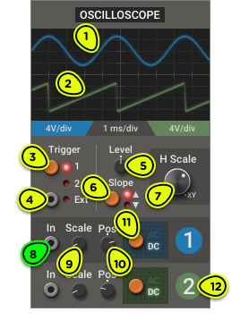
- Channel 1 Beam Shows the waveform of the signal connected to channel 1 In.
- Channel 2 Beam Shows the waveform of the signal connected to channel 2 In.
- Trigger Selector Selects which input signal will synchronize the display.
- External Trigger Input When the trigger is in Ext mode, a new display frame will be recorded when the signal crosses the trigger level.
- Trigger Level Knob Sets the voltage threshold for the synchronization trigger signal.
- Trigger Slope Selector Sets whether the display will synchronize when the trigger crosses the threshold on a descending or ascending slope.
- Horizontal Scale Knob Sets the horizontal scaling (also called time base) of the display. When fully clockwise, the display switches to XY mode.
- Channel Input Signal whose waveform will be displayed.
- Scale Knob Sets the vertical scaling of the channel in the display.
- Pos Knob Sets the vertical position of 0V for this channel in the display.
- AC/DC Switch Selects between AC coupling, which blocks the DC component and centers the signal around 0V, and DC coupling, which displays the unaltered input signal.
- Channel 2 Channel 2 has the same input and settings as channel 1.
Overview ⚓︎
This full-featured two-channel oscilloscope is designed to provide insight into the audio and CV signal flow of your patch—or simply gives you something pretty to look at while the patch plays.
Usage ⚓︎
Simple Periodic Signals ⚓︎
An oscilloscope works best for relatively simple periodic signals, like the output of an oscillator.
Connect the signal you want to observe to the In jack of channel 1.
Make sure that the trigger input is set to 1.
Set the horizontal scaling (H Scale) to an appropriate value for the signal.
Set the vertical scaling (channel-specific Scale knob) to an appropriate value for the signal.
If the display doesn’t synchronize properly, adjust the Trigger settings:
The Trigger Level knob sets the voltage at which the display will be synchronized. The level appears as an orange dotted line on the display.
The Trigger Slope switch determines whether the display synchronizes when the signal crosses the level while rising or falling.
Complex Periodic Signals ⚓︎
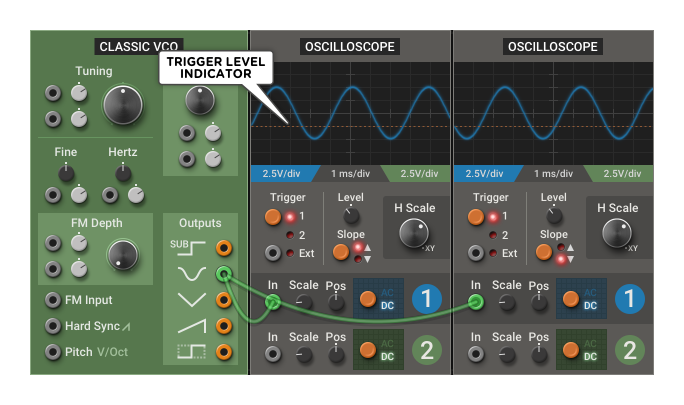
If the signal crosses the trigger level multiple times per period, the display may become unstable. In that case, the oscilloscope can be synchronized with an external trigger signal:
If the patch contains a plain oscillator running at the signal’s fundamental frequency, connect it to the Trigger—Ext input.
Make sure the Ext input is selected by clicking on the push button until its indicator LED lights up.
If the patch doesn’t have any plain oscillator at the right frequency, add a Classic VCO, connect it to the Ext input, and tune it to the input signal pitch. If you’re unsure of the pitch, slowly adjust the VCO Tuning knob until the waveform stabilizes.
When using an oscillator as an external trigger, try using a sawtooth as the source. That way, it will be possible to shift the waveform display horizontally using the Trigger Level between -5V and +5V.
Roll Mode ⚓︎
When the H Scale is set above 100 ms/div (or below 10 Hz), the oscilloscope enters roll mode. It will stop synchronizing to the trigger signal, and will allow the waveform to scroll horizontally at a slower rate. This shows the evolution of the signal over a long time span. It can be used to analyze CV signals like slow LFOs or envelopes, or to see the overall amplitude of an audio signal.
In this mode, the Trigger settings are ignored.
Dual-channel ⚓︎
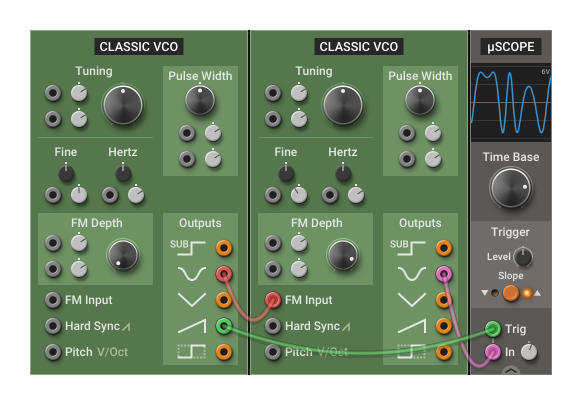
Unlike the µScope, this oscilloscope has two channels and can display two signals at once. This can be useful to compare the waveform, phase, or scale of two signals in your patch.
Simply connect another signal to the channel 2 In jack and adjust it as described above. If you don’t want the two beams to overlap, use the channel Pos knobs to move the beams vertically.
In dual-channel mode, both beams synchronize to the same trigger.
XY Mode ⚓︎
When the H Scale knob is fully clockwise, the oscilloscope enters XY mode, where channel 1 controls the beam’s horizontal position and channel 2 controls its vertical position.
XY mode can be used to check the relationship between two signals. If they are identical, the beam will trace a straight 45° line. If they have different waveforms, phases or amplitudes but their frequency ratio is an integer, the beam will trace a stable shape. If the signals' frequency ratio is close to an integer, it will trace an animated pattern. Uncorrelated signals will trace more chaotic patterns.
In this mode, the effect of the channel settings on the display is different:
- Channel 1 Scale changes the width
- Channel 2 Scale changes the height
- Channel 1 Pos changes the horizontal position
- Channel 2 Pos changes the vertical position
In the following example, we produce the Lissajous pattern by plotting two perpendicular sine waves at a 1:2 frequency ratio. We animate it by slightly detuning one of them.
In the Multiphonics Effect plug-in, XY mode can be used for oscilloscope music playback. Oscilloscope music is a genre where differences between the left and right channels in the stereo field produce interesting visuals on an oscilloscope.
If you have an oscilloscope music audio file, simply load it on a track in your DAW, insert an instance of the Multiphonics Effect plug-in, add an Oscilloscope module in the rack, set it to XY mode and connect the Input Left and Right jacks to channel 1 and 2 of the oscilloscope. Don’t forget to turn the Output Mixer Dry/Wet knob fully counterclockwise to hear the music play!
Oscilloscope music is very sensitive to compression artifacts, so make sure to use a high-quality uncompressed audio file, not a rip from a video stream.