Patching
Modular synthesis consists in producing sounds by connecting modules together with cables. These modules can generate or process audio and control signals.
The cables used to connect modules are called patch cables, the act of connecting modules is called patching, and the resulting creation is called a patch.
Building patches is done with these simple operations:
- adding modules,
- moving modules,
- removing modules,
- duplicating modules,
- connecting modules,
- disconnecting modules.
These are explained in depth in the Building a Patch section. But before going any further, let’s take a look at what you may find in a typical module.
Anatomy of a Module ⚓︎
Overview ⚓︎
The following image shows the characteristics and layout patterns that are found in most modules.
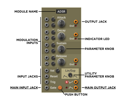
- Module Name Tells you what type of module you are working with. Right-clicking (or command-clicking on Mac) on the name will open a pop-up menu with the same commands as the Command Tray.
- Output Jacks Orange jacks, located on the right side of the module, are for output. The output jacks at the bottom-right of the module are usually the main output jacks, where you will retrieve the signal produced or modified by the module. Some modules, such as the ADSR shown above, have some extra outputs.
- Input Jacks Grey jacks, usually found on the left side of the module, are for input. Many modules need an input signal to work; for those modules, the main input jack will be found at the bottom-left. Some inputs are located near a big knob and have their own attenuverter1: they are called modulation inputs. These are explained in depth in the Modulation section.
- Parameter Knobs These knobs control how a module behaves. To adjust a knob, click and drag it up or down while holding the mouse button. Many knobs can be reset to their default value by double-clicking. For fine-tuning, hold the Shift key while turning. Most knobs have Modulation inputs located to their left or below, though certain utility knobs do not, such as the Lin/Exp shown above.
- Push Buttons These are used in some modules to manually trigger inputs (like in the ADSR shown above), or to switch between different modes of operation.
- Indicator LEDs These LEDs appear on many modules to show different aspects of their state.
- Command Tray The Command Tray arrow appears when the mouse hovers over a module. Clicking it opens the Command Tray.
Command Tray ⚓︎
The Command Tray is displayed by clicking on the small arrow that appears at the bottom of the module when the mouse cursor is over the module.
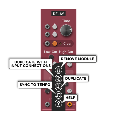
Remove Removes the module from the rack. Duplicate (with input connections) Creates a copy of the module with identical settings and input connections. This option is disabled if there isn’t enough space for another module in the same row. Duplicate Creates a copy of the module with identical settings but no connections. Sync to Tempo Synchronizes the module to the selected note division. This automatically connects the module’s rate or time knob to the Master Clock Tempo and adjusts it to match the selected note division. This feature is available only in modules with a single time-based parameter such as the Pulse, LFO, or Delay modules. Help Opens the online manual page for the module.
Not all commands are available for all modules. For example, in the built-in utility modules of the top row, only the Help command is available since these modules cannot be removed or duplicated.
Building a Patch ⚓︎
Adding Modules ⚓︎
Modules are found in the module browser. If the module browser is not currently visible, clicking in an empty part of the rack will show it.
A module is added by drag-and-dropping it from the browser, or by clicking on the + button next to the module image at the bottom of the panel.
When using drag-and-drop, the location where the module will be inserted is shown with an orange bar. Otherwise, the module will be inserted in the last row where you clicked in an empty spot.
Moving Modules ⚓︎
When your patch gets too complex, you may want to reorganize the modules in a different order to make it clearer. You can move a module by clicking on its name, holding the mouse button down and dragging it to the desired location.
The location where the module will be moved is shown with an orange bar. If no orange bar appears, there may not be enough space in the row. In that case, try dragging the module to a different row.
Removing Modules ⚓︎
A module is removed by clicking on the Remove icon in the Command Tray.
Duplicating Modules ⚓︎
An existing module can be duplicated by clicking on the Duplicate or Duplicate (with input connections) icon in the Command Tray.
- Duplicate Creates a copy of the module to its right, with the same settings.
- Duplicate (with input connections) Creates a copy of the module to its right, with the same settings and input connections.
Connecting Modules ⚓︎
To connect modules, click on an output jack (orange), hold the mouse button, and drag the patch cable to an input jack (grey).
An output jack may have many cables connected into it, so the same source can easily be sent to different parts of the patch. However, an input jack can only have one connection.
To connect many different sources into the same input jack, add a mixer, like the Mix 8 module, connect all sources into the mixer input, and connect the mixer output to the targetted input jack. The mixer will also let you adjust the relative volume of each source.
The following video shows how to create a very simple synth by connecting the sawtooth output of a Classic VCO to a VCA input, the output of the VCA to the audio output, the Keyboard Gate to the VCA CV input to let sound through when playing a note, and the Keyboard Pitch to the VCO Pitch for note tracking.
If patch cables obscure important controls in some modules, you can make them transparent or invisible by changing the Cable Opacity setting from the View menu in the toolbar.
Multiphonics does not impose any restrictions on how the modules are connected to each other. A patch can have any number of feedback loops, and a module can even be connected to itself.
The Advanced Features section presents quicker ways to do stereo, multi-channel, and CV patching.
Disconnecting Modules ⚓︎
There are three ways to disconnect patch cables:
- For input jacks only Click and hold the left mouse button and move the cable to an empty spot of a module, or to another input jack to reconnect it there.
- For any jack Double-click on the jack. For outputs with multiple connections, this will remove them all.
- For any jack Right-click (or command-click on Mac) on the jack and choose Delete Cable from the pop-up menu.
Saving Patches ⚓︎
When you like what you hear, you can save your patch to the User collection of the patch browser by clicking on the Save button in the toolbar.
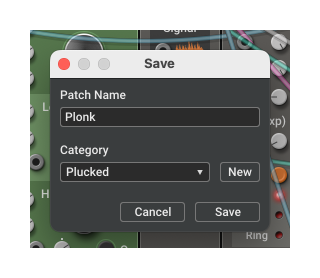
Enter the patch name in the text field at the top, choose a category from the drop-down list or create a new one with the New button, and click on Save to save the patch to your User collection.
A patch file stores everything you see in the rack (modules, connections, knob settings).
The factory and sound pack collections are read-only. If you modify and save a patch from one of these collections, it will be stored in your User library. When showing all patches in the browser, the saved patch will appear twice: once with [User], and once with [Factory] (or sound pack name) appended to its name.
When using Multiphonics as a plug-in in a DAW, the rack contents are automatically saved with the DAW project. This means modified patches and one-off patches created for a single project don’t need to be saved in your Multiphonics user library.
Video Tutorials ⚓︎
The quickest way to get a hang of patching is to fire up Multiphonics and build some patches. To help you get started, we created some video tutorials you can follow:
https://www.applied-acoustics.com/l/multiphonics-cv-3-video-tutorials/
Advanced Features ⚓︎
This section presents alternative patching techniques that aren’t essential to know but can save time for power users.
CV Quick-connect ⚓︎
You can quickly connect many standard CV inputs to their most likely source by double-clicking on them.
This only works on CV inputs (grey jacks), not on outputs (orange jacks).
Keyboard-related CV Inputs
In general, any gate, trigger, pitch, or velocity CV input will connect to the corresponding Keyboard output.
However, if a module producing one of these signals is located anywhere to the left of the module being quick-connected, it will take priority over the Keyboard. For example:
- Gate and trigger inputs will connect to any sequencer’s gate and pulse outputs or to the Pitch Detector’s sensor and trigger outputs
- Pitch will connect to a Gate + CV Sequencer’s CV output, to a Pitch Detector’s pitch output, as well as to pitch-filtering modules like the Glide and Quantizer.
Clock-related CV Inputs
In general, any clock, tempo or play CV input will connect to the corresponding output from the Master Clock.
However, if a Clock module is located anywhere to the left of a module whose clock-related inputs are being quick-connected, they will connect to that Clock module instead.
As a special case, the Master Clock play input (labeled In) will auto-connect to the Keyboard gate output so that the clock starts when a note is played.
Other CV Inputs
Some modules have CV inputs that can quick-connect to various signal outputs from modules located to their left. Most importantly:
- VCA and LPG CV inputs will either quick-connect to the nearest envelope located to its left, or to the Keyboard Gate output.
- LPG Ping input follows the same rule as trigger inputs.
- Reset inputs (outside of Clock modules) follow the same rule as trigger inputs.
- Per-operator Env inputs in 3-operator Digital FM connect to the nearest envelope to its left, if one exists.
Quick-connect Example
In the following video, we can see the gate, trigger, velocity and pitch CV inputs being quick-connected to the Keyboard module, and the VCA CV input being quick-connected to the µADSR output. Only the audio signals need to be connected manually.
Multi-patching ⚓︎
In some situations while you are pulling a cable, Multiphonics will show one or more extra dotted cables. If you press the Shift key before you release the mouse button to complete the connection, all of the suggested connections will be made. This can be a real time saver for stereo or multi-channel patches.
This section describes various scenarios where you might encounter this option.
Stereo to Stereo
To connect two stereo modules together in one action, pull the cable from the left channel of the source and connect it to the left channel of the destination while holding down the Shift key.
The following video shows how to create a simple stereo effect patch with the Objeq Filter module, using the Shift key for quicker stereo patching. Notice how we pan the left and right channels in the Output Mixer to preserve the full stereo width of the processed signal.
Stereo to Dual-mono and Vice-versa
While most audio processing modules are stereo, some utilities can still be mono. In that case, stereo connections are still possible as long as the two mono modules are placed next to each other. Pull the cable from the left output channel of the stereo source, and connect it to the leftmost mono module.
Dual-mono to stereo connections can also be achieved by pulling the cable from the output of the leftmost mono module and connecting it to the left input channel of the stereo module.
The following video shows how to build a polarity inverter with two Inverter modules, taking advantage of stereo to dual-mono and dual-mono to stereo patching.
One to Many
It is often useful to connect a single CV-source to multiple identical modules. For example, in a synthesizer, you may want to connect a pitch signal to many oscillators. As long as the target modules are identical and are next to each other, Multiphonics will offer to make multiple connections with the Shift key. To connect to all modules, pull the wire from the source to the input of the leftmost destination module.
In the previous example, note how the third Compact VCO was not connected to the pitch, since it was not contiguous with the first two.
Many to Many
When designing a synth with multiple voices, you may end up in a situation where you need to connect 3 oscillators to 3 filters, then 3 filters to 3 VCAs, and so on. You can take advantage of the Shift action to do all connections at once as long as the following is true:
- the source modules are identical,
- the source modules are next to each other,
- the destination modules are identical,
- the destination modules are next to each other,
- there are the same number of source and destination modules,
- the cable is pulled from the leftmost source to the leftmost destination.
Many to One
Multiphonics will also offer to connect the output of multiple identical modules into a single multi-input module like a mixer. Pull the wire from the output of the leftmost source module to the first channel where you want that connection to go. The other modules will be connected to the subsequent inputs.
This video shows how to connect four oscillators playing different tones to the four channels of the Output Mixer using the Shift key.
…and Many More
Only the most common scenarios have been described here. The more you use Multiphonics CV‑3, the more you’ll get a better feel of what is possible with the Shift action.
Caveat
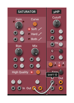
Some patching situations can match more than one of the scenarios described above. For example, in the following image, Multiphonics offers to patch the second Saturator to the second µHP, but it could also have offered to patch the right channel of the first Saturator to the right channel of the first µHP.
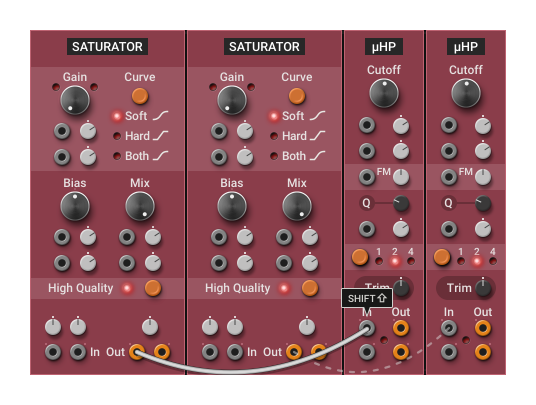
While designing this feature, we had to arbitrarily choose what connection to suggest when we encountered situations such as these. Because of that, in complex patches, you may encounter situations where the suggested connections are not what you need. In that case, you will have to make those connections manually, without the Shift action.
Multi-module Parameter Changes ⚓︎
If the patch contains multiple modules of the same type next to each other, you can change a parameter in all modules by holding down the Alt key while turning a knob or clicking on a push button.
For knobs, the movement will be relative to the initial knob position in each module. For example, if you had two oscillators with their frequencies set to C and G, and you turned the C knob up to E, then the other oscillator would now have its frequency set to B, thus keeping the same relative interval between the two oscillators.
For knobs that have default values, double-clicking while holding Alt will set the default value in all modules.
For switches and selectors controlled with push buttons, all modules will synchronize to the same value.
In the following video, all parameter changes are done with the Alt key held down. It shows:
- a plain multi-module parameter change on the Gain knob,
- the behavior when the initial knob position is different on the Bias knob,
- how to set the default value on both modules by double-clicking on the Bias knob,
- the behavior for selectors with the Curve push-button, starting with a different value.
-
Attenuverter is a contraction of the words attenuator and inverter. An attenuverter is a special kind of volume knob. When it is centered (0%), the signal is blocked. When it is turned clockwise from the center position, it behaves like a normal volume knob up to 100% where it lets the whole signal through. When turned counterclockwise from the center position, it will also act like a volume knob, but it will invert the signal polarity as well. For example, at –100% (fully counterclockwise), an input of 5V would become –5V. ↩︎